Introduction
This practical work contain a scenario description and exercises to endow students with practical experience in software modeling using the Unified Modeling Language (UML).
Scenario Description
A mining company plans to change how its cyber-physical environment is controlled as part of its digital transformation. The plan involves implementing the most appropriate techniques to ensure the scalability, maintainability and security of its production system.
You have being assigned the task of leading a team to carry out the digital transformation of the conveying system for iron ore. Currently, the conveying system is composed of multiple conveyors, each controlled by a manually parameterized PLC. The goal is to automate the conveyor system enabling the remote control of the conveyors and their integration into the company’s information system.
The conveyors transport iron ore from the storage areas (i.e., loading areas) to iron ore carrier ships (i.e., unloading area). Each conveyor transport iron ore to one carrier ship, but multiple conveyors can transport iron ore to the same ship. The loading of iron ore at the loading area is carried by a crane operated by an operator. A single crane loads each conveyor. New automated conveyors have been acquired and installed, they are equipped with sensors to detect when there is any minimum load on the belt. The belt automatically stops when there is no load on the belt or runs when there is a minimum load on the belt. The belt can move at different speeds. The conveyor operator is responsible for setting manually the conveyor belt’s speed and for stopping the conveyor whenever the carrier ship is completely loaded.
Technicians maintain or repair the conveyor system. Maintenance includes upgrade of hardware, firmware or software, and remote or on-site diagnostics.
Exercises
Using paper and pen or any drawing tool, such as Lucidchart or Draw.io, complete the exercises according to the Scenario Description.
-
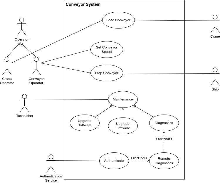
UML Use Case diagram
-
Identify the actors
-
Identify use cases
-
Draw the corresponding Use Cases diagram
-
-
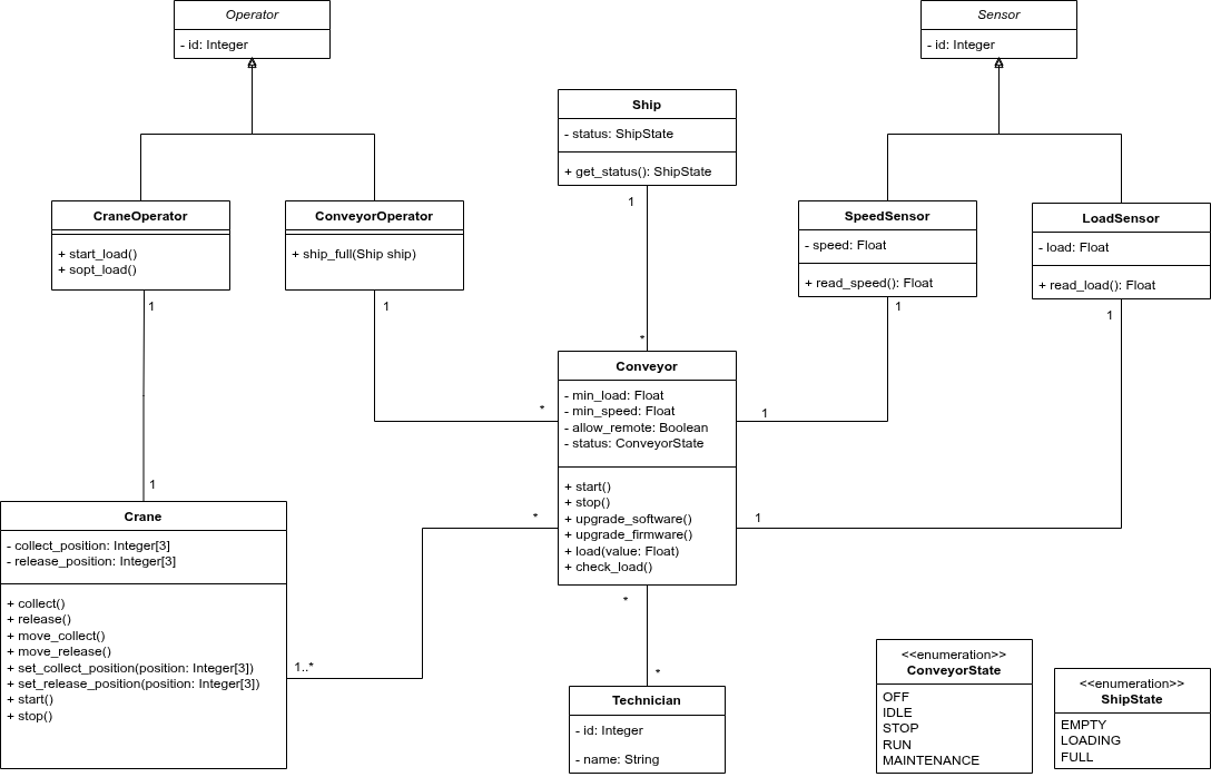
Draw a UML Class diagram
-
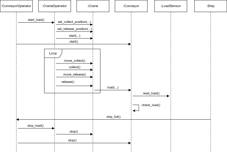
Draw a UML Sequence diagram of the loading of a iron ore carrier ship
-
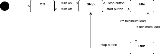
Draw a UML State Machine diagram of a conveyor